The project
When incompetencies in the rock were discovered, Keller was contracted to perform several techniques from their tunneling toolbox to keep operations on track.
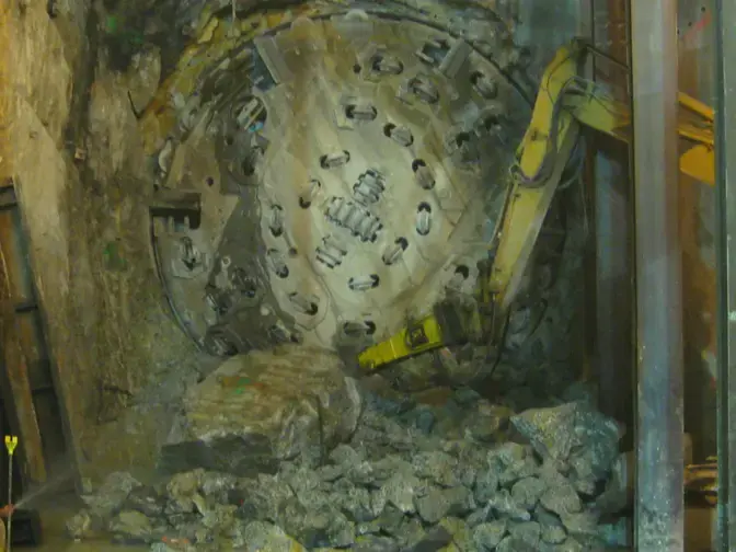
An extension of the No. 7 Subway Line in downtown New York City comprised 1.5 miles of twin, 22-ft-diameter tunnels bored through rock with a terminus at 34th Street and 11th Avenue. The 200-ft-long receiving chamber for the two tunnel boring machines (TBMs) was excavated immediately below the Port Authority Bus Terminal. When incompetencies in the rock were discovered during boring operations, Keller was contracted to perform mitigative ground modifications to keep tunneling safely on track.
The solution
Compensation (fracture) grouting
Traditional vertical borings and horizontal cores taken from inside the tunnel indicated a limited rock cover between the end of the tunnel drive and the receiving cavern entrance. The rock was also highly fractured above the one TBM alignment. Additionally, the pillar between tunnels was only one-half tunnel diameter wide. Keller was called in by the project’s general contractor, S3 II Tunnel Constructors, to perform stabilization grouting in preparation for the passing of the first TBM.
Given the nature of the fracturing, Keller recommended the use of microfine cement grout for stabilization. The entire staging, drilling, colloidal mixing, and grouting operation was accomplished in low-headroom conditions within the active, basement-level passenger pick-up/drop-off area of the Port Authority bus terminal. S3 II removed the concrete roadway bed over the target zone and excavated the base material to the top of the rock.
Keller used a low-headroom rotary rig with a down-the-hole hammer to drill to the tunnel springline from 24 ft below working grade. Each hole was water-tested before grouting to determine the rock's permeability. A 1-inch diameter fiberglass bar with centralizers was inserted for the full length of the hole before grouting to aid in tying the rock together as a single mass. Grouting was initiated at the holes with the highest permeability. Grout was pumped at a maximum pressure of 25 psi until absolute refusal.
Ground freezing
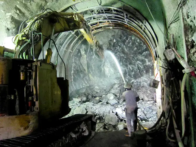
A previously unidentified dip in the competent bedrock required the tunneling contractor to modify the ground to solidify the envelope above the tunnel. Ground freezing was chosen as the safest and most assured ground modification method to support the tunnel section's hand mining. Ground modification and hand mining were performed to safely maintain stability, restrict groundwater inflow, and limit settlement of the overlying structures.
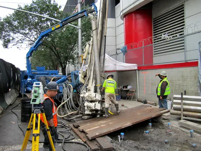
The ground freeze design incorporated drilling and installing 25 angled freeze pipes, field located, to depths ranging from 80 ft to 110 ft. The welded steel freeze pipes were installed using a dual rotary drill rig capable of providing the steeply angled cased holes to reach the target zone. The locations were precisely selected to avoid the many utilities under Eleventh Avenue. In addition, three pipes designed to obtain ground temperatures were installed in proximity. These temperature monitors were field-located based on the actual freeze pipe alignment.
Each freeze pipe was connected to supply and return headers via a custom freeze head. The supply and return headers were piped directly into the refrigeration unit, which circulated the coolant calcium chloride brine and delivered to the freeze pipes, extracting heat from the ground. The soil strength in the freeze zone varied with the distance from an active freeze pipe, typically between 400 and 600 pounds PSI.
The monitoring program consisted of daily measurements and graphical representations of the ground temperatures gathered from the three temperature monitor pipes. During the formation and maintenance of the frozen ground, the thermocouples were measured daily to provide assurance of the ground freezing progress.
Once the data from the temperature monitors indicated that the soil mass within the tail tunnel excavation had reached the target temperature, the contractor began removing the rock along the alignment using line drilling and an excavator-mounted hydraulic hammer. A staged excavation sequence, composed of six five-foot zones, was developed. This allowed for a timed deactivation of freeze pipes within the excavation envelope and the installation of rib beams and shotcrete.
The ground freezing system was deactivated upon completion of the work, and the surface components were removed from the site. The freeze pipes were then abandoned by Tremie grouting in place.